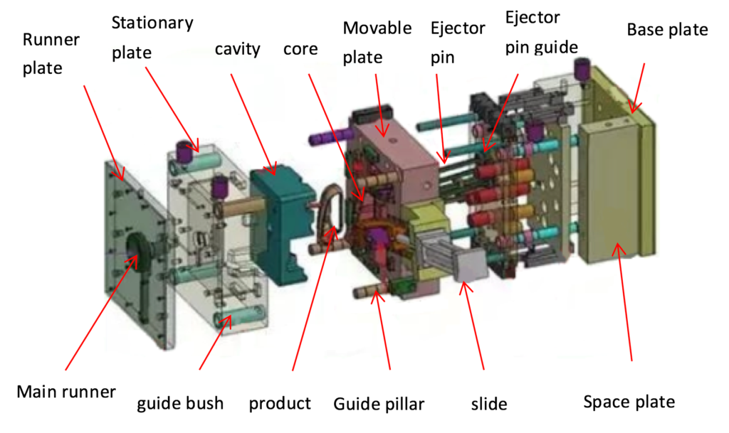
Injection moulding tool – structure and function
In general, the structure of the tool is quite same across the board for all injection moulding tool. Each and every injection moulding tool is always made up of two halves, which are referred to as the nozzle side and the ejector side, which is located opposite the nozzle side. Both parts of the tool include the different components that make up the tool. These components include the ejector elements, the sprue systems, the cores, cavity inserts, and the cooling (or temperature control) system. Commonly Injection moulding tool is used in Injection molding machines.

Every injection moulding tool is made up of three fundamental modules and the subgroups that correspond to each of those modules. Among these are techniques for controlling the temperature, casting technology, and demoulding procedures. A selection of the unique design is the fourth feasible criterion to take into consideration.
Forming injection molded parts with two tool halves
It is common practice for a simple injection mould to consist of two halves, each of which is composed of additional plates. It is always the case that the nozzle side of an injection mould is the static half of the mould, which means that it does not move while the injection moulded pieces are being manufactured. Within this nozzle-side tool plate, the so-called mould cavities, which are also known as mould inserts or half-shells of the cavities, are typically inserted. Other names for mould cavities are mould inserts and mould cavities.
In addition, the components that are a part of the sprue system are located on the side of the nozzle. Included in this category is the sprue bushing, which is typically linked to a cold runner distribution system. In the event that it is present, the hot runner distributor, which is a type of hot runner nozzle that is utilised in cascade injection moulding, is likewise located on the side of the nozzle. An interchangeable centering ring is used to secure the platen of the machine to which the injection moulding tool is mounted in its entirety.
By means of this centering ring, the nozzle tip is submerged in the tool while the production process is taking place. At that location, it is forced against the bushing of the sprue. An additional insulating plate is mounted in front of the clamping plate if the tool in question is an injection moulding tool that operates at higher mould temperatures. This acts to prevent heat exchange with the clamping plate that is located on the machine side.
Ejector elements, shaping cores, and inserts, which are commonly referred to as cavities, are all contained on the ejector side of an injection moulding tool. This side is also known as the cavity side. The moulded part will typically remain in the ejector side of the tool even after it has been opened. When it comes to demolding, also known as ejecting the moulded item from the mould, various ejection devices are utilised, depending on the degree of difficulty involved. Because of this, it is essential to ascertain, during the planning stage of the injection-moulded component, the kind of demoulding that will be required at a later stage in the manufacturing process. In this location, you can choose from the following choices:
Ejector pins are a useful tool for removing injection-molded parts that do not have undercuts. These parts can be stripped or pulled off and removed from the mould.
Parts that have been moulded through injection and have undercuts are extracted from the mould by means of slides or jaws.
In the event that injection-molded components include either an internal or exterior thread, it is possible to employ forceful demolding, demolding with collapsible cores, or demolding with rotating cores technique.
Temperature control tool
Both mould halves of the injection moulding tool are equipped with a temperature control system that can be controlled independently, which helps to ensure that the temperature is precisely controlled. The plastic that is going to be processed determines the temperature at which the tool is set.
Image Credit:- https://mavink.com